A.G Brake Motor introduction & application
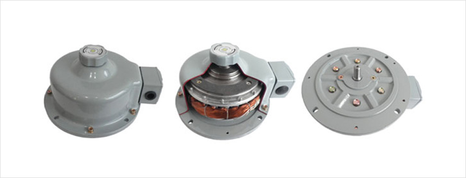
AXIAL AIR GAP BRAKE MOTOR
There are 3types of structure, normal type, air lock type and Gondola type. AXIAL AIR GAP BRAKE MOTOR is used for precision machine tools by high braking torque(350%). Air Lock type has strengthened the braking function by adding a pneumatic cylinder in the conventional brake method. Gondola type is connected cable and has cap for protect switch
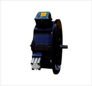
▲ Air-Lock Type
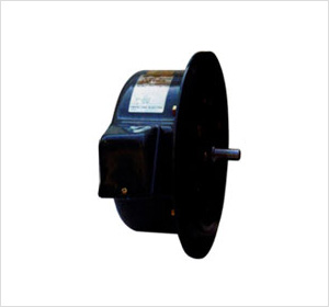
▲ Normal Type
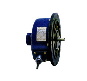
▲ Gondola Type
Information
| Item | Detail | ||
|---|---|---|---|
| Time Rating | 5 minutes ~ Contiuous | ||
| Output Power | 0.1kw ~ 5.kw | ||
| Insulation | B & F Class | ||
| Construction & Protection | Construction | Protection | |
| TEFC | IP44, IP54 | ||
| Auailable Voltage | 200~ 460volt Single Voltage, Dual Voltage, Combination Voltage |
||
| Frequency | 50Hz , 60Hz, 50/60Hz | ||
| Painting | Munsell No. 7.5BG 6/1.5 | ||
| Lining Material | Non - Asbestos | ||
| Rotation | C.C.W(View of Drive End) | ||
| Ambient Condition |
Temoerature | -20℃~ + 40℃ | |
| Humidity | less than 80% | ||
| Altitude | less than 1,000M | ||
| Place | Non Corrosive, Non Explosive, Non Hymidity, No Dust | ||
Characteristic
- 1Optimized design integrated, light, compact.
- 2Strong start power with high torque.
- 3Excellent insulation system. (Insulation H class)
- 4Excellent positioning with 350% braking torque.
Application
- 1Press slide
- 2Hobbing Machine
- 3Machine tool, Automatic door for parking lot
- 4Industrial Gondora
A.G Brake Motor detailed designation
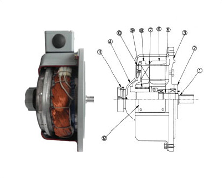
| No | Part Name |
|---|---|
| 1 | Shaft |
| 2 | Bearing Cover |
| 3 | Flange |
| 4 | Motor cover |
| 5 | Bearing Gap |
| 6 | Stator |
| 7 | Air Gap |
| 8 | Rotor |
| 9 | Spring |
| 10 | Break Lining |
| 11 | Break Release Handle |
| 12 | Lead Box |
Torque Specification
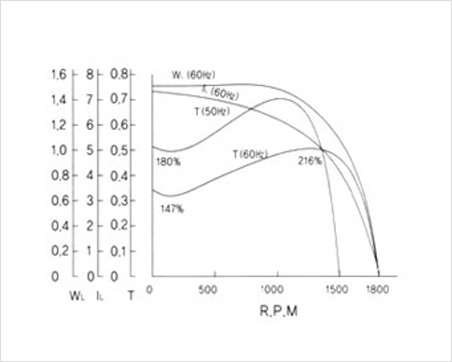
- 1220v/50Hz/60Hz test data
- 2WL : Voltage(Kw)
- 3IL : Electric current(A)
- 4T : Torque(kg.m)
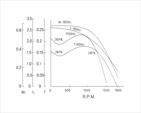
▲ 0.1Kw
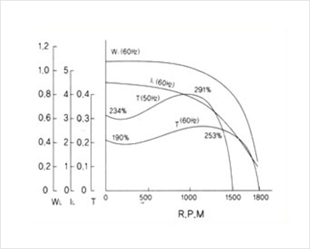
▲ 0.2Kw
▲ 0.4Kw
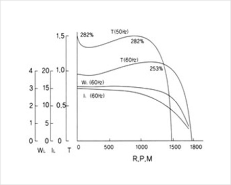
▲ 0.75Kw
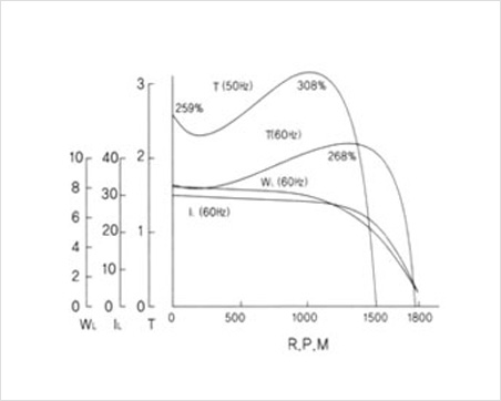
▲ 1.5Kw
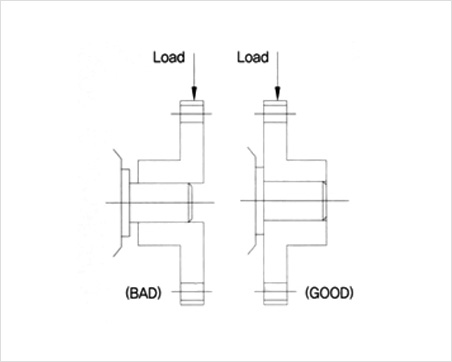
Allowable Pressure Load
When connecting the motor, the weight to be loaded on the shaft and the overhang weight should not exceed the allowable pressure load weight (follow the table bellow).
| Output | Pole | Thrust Weight |
Overhang Weight |
|---|---|---|---|
| 0.1Kw | 4 | 25 | 30 |
| 0.2Kw | 4 | 30 | 40 |
| 0.4Kw | 4 | 30 | 40 |
| 0.75Kw | 4 | 50 | 65 |
| 1.5Kw | 4 | 70 | 90 |
| 2.2Kw | 4 | 70 | 90 |
Caution
When fixing gears, pulleys and sprockets to the shaft, use shrink fit method, not the hammer fit method to prevent impact to the shaft.
| Item | Check cycle | Note |
|---|---|---|
| Re-injecting grease at the joint of the fitting (Reducer) | 1000 to 2000 hours | Brake Lining Replacement |
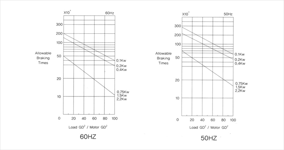
| Brake Lining Replacement | Graph reference | |
| Check the inside of the motor cover | Same as lining and replacement time | |
| Re-inject grease between motor shaft and rotor | 5000 to 6000 hours | |
| Abrasive angle between motor shaft and rotor | 5000 to 6000 hours | |
| Thrust Ball Bearing Re-Grease | 5000 to 6000 hours | |
| Exchange of Deep Groove Ball Bearings | 2 years | |
| Thrust Ball Bearing Replacement |
10000 hours (0.1 ~ 0.4Kw) 6000 hours (0.75Kw ~) |
Brake linings wear out after long-term use, and the use of worn linings causes performance degradation. Brake ling wear is related to usage time. load value(GD2), motor capacity, and condition of operating. Refer to the graph below and replace the lining according to the allowable brake braking time of each motor.